
Process or manufacturing plants have PLCs which get signal inputs from mechanical buttons, switches, limit switches and send signal outputs to activate relays, solenoid valves etc. In many cases, they use 24V DC power supply for PLC CPUs and their I/O modules. This voltage level is used for input modules and deliver 24VDC from output module to turn solenoid valves, coils etc.
For non-critical use and ignoring the latency , we can build simple 5V to 24V DC I/O adapter that can be used with our Microcontrollers to drive 24V DC rating relays and supplying switches/buttons.
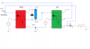
Don’t get confused with the schematic above . Yes, it works !. The reason there are two “opto couplers” above ( Actually only one opto coupler with two sockets which I will explain later) is that we can use GPIO from our Microcontrollers, AVRs, Arduino boards etc like we intended. For example we can use Pin 1 as input OR as output from the same block diagram above. Let says we have 8 I/O pins, each pin will go to both red and green block so we just need to focus on our code/program without worrying which one is for input or output.
HOW IT WORKS:
(See the picture) The main part here is 4N29 opto coupler that can “convert” either 5V DC to 24V DC or from 24V DC to 5V DC. The red square on the picture is a 4N29 socket for output ,and the green one is a socket for input. We have two sockets but we only need one opto coupler IC . When output signal needed , move this IC to the red socket, otherwise we just leave it on green socket. Never put two ICs on both sockets at same time to avoid input/output conflicts. The inputs/output devices will be connected to blue square terminal block. Put the relays, bulbs, solenoids, switches, and buttons there .