
In the old days, We used to have electronic controllers or PLCs to send the warnings or alarms on the panel by turning combination of light indicators on or off. To understand these signals we have to refer their operation manuals to interpret these messages. For example if they have three indicators on the panel which has Light A(LA), Light B(LB) and Light C(LC), it will be 2^3 =8 combinations of warning/alarms. To make it easy to understand , they provide us a troubleshooting table to tell operators or technicians to trace the problem.
LA=0, LB=0, LC=0 -> ” Machine OK” ,
LA=1,LB=0, LC=0 -> ” Motor Overload” ,
LA=1, LB=1 ,LC=0 -> “Motor Overtemperature”,
etc, etc
(0 =OFF, 1 =ON) .
I am sure such devices or control panels still exists and still be produced today. Sometimes it is not easy to troubleshoot the problem because of missing manuals or any other reasons. For this purpose we will design and build Alarm messaging system using Arduino to retrofit old panels and to convert light bulb/LED indicators into a LCD display. Here is the example. Let says that we had an old PLC that control the following system (pic1). The ladder diagram showed here just to demonstrate how to manipulate 3 coil or relay outputs. Of course we can build more than 3 outputs when we need it.
.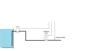
Pic.1
The ladder diagram looks like this :
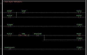
Pic2.
Basically, this program tell us to open the valve 5 seconds before turning the centrifugal pump on. When we press “Xstart” button, it will open the valve. The Ylight1 will turn on after valve open limit switch (XLSopen) become true. Ylight2 shows the pump is running meanwhile Ylight3 indicate that there is low pressure(XLowPressure) on discharge line.The normal operation should give us Ylight1=1, Ylight2=1 and Ylight3=0. This means valve is fully opened, motor is running and we got normal pressure. Since we can make 8 combinations from these lights, We can convert these states into meaningful messages with Arduino. There is two options to use Arduino for this purpose. The first one is just for converting the state of indicators into messages. Secondly it can be utilized as both PLC and warning/alarm messages. We will use the later for this example.
Things we need to build this Project:
- Arduino Board.
- Arduino IDE.
- LCD display (serial or I2C) with Arduino Library.
- LDMicro.
- PHP script to build Arduino Library header (optional).
Any Arduino board can be used for this project. All I/O will be configured using Arduino header. Download LDmicro from this site : http://cq.cx/ladder.pl
The beauty of this LDmicro is that we can compile the ladder diagram into ANSI- C code and from this cpp format we can build the library for Arduino IDE.
For PHP script to generate a header we can get it from here : https://github.com/ah01/LDmicro2arduino
Please remember to run php script, we need to install PHP program in our computer. For PHP for windows download the program here : http://windows.php.net/download
Now Lets modify the ladder diagram from pic1.
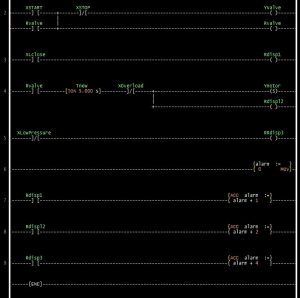
When we look at new ladder diagram, there are some changes and some rungs additions which have accumulator instruction (Acc ) inserted to them. These four extra rungs actually to convert binary status into decimal, Binary Coded Decimal (BCD). From three coil status, we can generate 8 messages.
Save this ladder diagram as ladder.ld ( we can choose any name for this file). Next step is to choose a microprocessor. On “Setting”->”Microcontrollers” , choose ANSI-C code. Then go to “Compile” ->”Compile as… ” and save it as ladder.cpp. Click OK and it will shows :
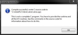
Don’t worry about this warning. Like it said on pop-up window, this is not complete program so we have to build header by itself. C/C++ programming skills is not really needed. Just use this cpp together with header we are going to build to create a library to be used in Arduino IDE.
Now It is time to build a header(Ladder.h) The header below built using ladder-gen.php ( see previous link above to download it). Follow instruction there how to run and to build a header for Arduino. We can see that all I/O pins fo Arduino can be configured here.
- #ifndef LADDER_H
- #define LADDER_H
- #if ARDUINO >= 100
- #include "Arduino.h"
- #else
- #include "WProgram.h"
- #endif
- #define BOOL boolean
- #define SWORD int
- #define EXTERN_EVERYTHING
- #define NO_PROTOTYPES
- EXTERN INT U_i_arduino;
- void PlcCycle(void);
- /* Configure digital I/O according to LD (call this in setup()). */
- inline void PlcSetup()
- {
- pinMode(11, INPUT);
- pinMode(12, INPUT);
- pinMode(5, OUTPUT);
- pinMode(9, INPUT);
- pinMode(6, OUTPUT);
- pinMode(10, INPUT);
- }
- /* Individual pins (this code is used in ladder.cpp) */
- inline extern BOOL Read_U_b_XSTART(void)
- {
- return digitalRead(11);
- }
- inline extern BOOL Read_U_b_XSTOP(void)
- {
- return digitalRead(12);
- }
- inline BOOL Read_U_b_YValve(void)
- {
- return digitalRead(5);
- }
- inline void Write_U_b_YValve(BOOL v)
- {
- digitalWrite(5, v);
- }
- inline extern BOOL Read_U_b_XLSopen(void)
- {
- return digitalRead(9);
- }
- inline extern BOOL Read_U_b_XOverload(void)
- {
- // TODO
- }
- inline BOOL Read_U_b_Ymotor(void)
- {
- return digitalRead(6);
- }
- inline void Write_U_b_Ymotor(BOOL v)
- {
- digitalWrite(6, v);
- }
- inline extern BOOL Read_U_b_XLowPressure(void)
- {
- return digitalRead(10);
- }
- #endif
To write an Arduino sketch, the first step is to create a new folder. Name it as “Ladder” and put both ladder.cpp and ladder.h inside this folder. Copy or move it into Dir://Path/to/Arduino/libraries.
It ‘s time to write an interesting sketch in Arduino IDE.
- #define _Digole_Serial_UART_
- #include "DigoleSerial.h"
- DigoleSerialDisp mydisp(&Serial1, 9600);
- #include "ladder.h"
- /* Plc cycle interval, set this according to LDmicro settings. (micro sec.) */
- #define PLC_INTERVAL 10000
- #define LCDCol 16
- #define LCDRow 2
- int ptr;
- const char a[] = "Arduino PLC";
- void setup()
- {
- mydisp.begin();
- mydisp.clearScreen();
- mydisp.disableCursor(); //disable cursor, enable cursore use: enableCursor();
- // mydisp.drawStr(4, 0, "Testing");
- mydisp.setPrintPos(2, 0);
- mydisp.print(a); // display a char array
- // resetpos();
- {
- PlcSetup();
- }
- }
- void loop()
- {
- if (IsPlcInterval())
- {
- PlcCycle();
- switch (U_i_alarm) {
- case 0:
- mydisp.drawStr(4, 1, "Valve closed");
- break;
- case 1:
- mydisp.drawStr(4, 1, "Valve opened ");
- break;
- case 2:
- mydisp.drawStr(4, 1, "Check if valve is OK ? ");
- break;
- case 3:
- mydisp.drawStr(4, 1, "Pump and Valve OK ");
- break;
- case 4:
- mydisp.drawStr(4, 1, "Low Pressure , Valve and Pump off ");
- break;
- case 5:
- mydisp.drawStr(4, 1, "Low pressure , check Pump! ");
- break;
- case 6:
- mydisp.drawStr(4, 1, "Low pressure , check Valve! ");
- break;
- case 7:
- mydisp.drawStr(4, 1, "Low pressure , check the line/leak ");
- break;
- }
- }
- }
- /* Plc Cycle timing function. */
- boolean IsPlcInterval()
- {
- static unsigned long last_run;
- if (micros() - last_run >= PLC_INTERVAL)
- {
- last_run = micros();
- return true;
- }
- return false;
- }
In the example above we use Digole serial LCD to display the messages. The good thing about LDmicro is that it much easier to create ladder program and then modify in the future with no change or few change in Arduino sketch itself. As long we have same numbers of I/O pins we don’t need generate a new header, what we need is just to compile a new ladder ( newladder.ld) and to save it as newladder. cpp then to copy it to an arduino library folder.