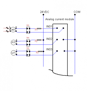
Here is a part of simplifying of PLC wiring diagram at a water treatment plant (see picture above). There are three transmitters that connect to a PLC analog current input module and with some reasons, they mysteriously failed to work at the same time at the same PLC module. Of course this event is rarely happened in real instrumentation field !. This example just to give idea what we are going to encounter in the field and how to solve these problems.
Most 4-20 signal generators or process meters sold in the market provide basic modes such as: source, simulate and to generate at least 24 Vdc for powering the loop. We will use our tool: 4inONE-4to20mA signal generator and a trainer in these examples.
Case 1.
A Cl2 Analyzer device powered by 110 VAC (AIT). The range was between 0 -10 mg/L(ppm). It showed 4.9 mg/L on device display itself but it showed 0 reading on SCADA monitor.
-> Check the analog output of Cl2 Analyzer. If the current reading shows approximately 12 mA, the problem should be somewhere else than the transmitter itself. Check the fuse and wire, make sure no blown fuse or broken loop. Open the loop, remove Isolator block (iso) and connect the probes in “SOURCE” mode like showing on the picture A. ON android app, set the source to “12” mA.
 Picture A.
If SCADA reading shows around 5 mg/L, the most likely failure come from Isolator block, otherwise we might have a faulty PLC analog current module.
Case 2.
A two-wires Flow Meter(FIT) which has range: 0-10 MGD indicated 8.75 MGD on its display but only showed 2.5 MGD on SCADA monitor.
->Let find both values in mA.
mA= (U/Ufs*16) +4
mA=reading in mA, U=reading in MGD , Ufs=Full scale of MGD
mA1=(2.5/10*16)+4 = 8 mA , mA2 =(8.75/10*16)+4 = 18 mA
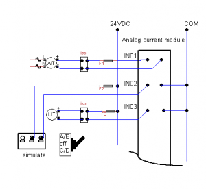
To verify PLC input module that connect to two-wire transmitter, we need to connect the probes on “SIMULATE” mode like showed on picture B. Set android app to “18” mA. Make sure there is no blown fuse or broken loop. If SCADA monitor shows much less than 8.75 MGD, The problem might come from a bad PLC input module or PLC/SCADA scaling errors.
 Picture B.
Case 3.
.A two-wires Level Transmitter (LIT) will shut down intermittently and will show erratic current readings.
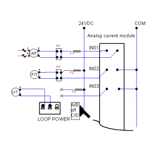
-> Check Transmitter operation by connecting probes on “LOOP POWER” mode . (picture C). Monitor current reading on Android app.
 Picture C.
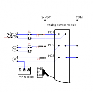
Replace Level Transmitter if the problem persists. If not continue to next step. Remove isolator and check existing 24 Vdc voltage. Using autographic and data logging on Android app, connect the probes like showed on picture D. Monitor current loop trending without isolator block installed.
 Picture D.
note:
AIT = Analytical Indicating Transmitter
FIT =Flow Indicating Transmitter
LIT =Level Indicating Transmitter
